BF2 Development Board (Wi-Fi/BLE)
Product Description
Parameter
Target Applications
Terminal Devices
Applications
Documentation
Features
Content 1
Content 2
Content 3
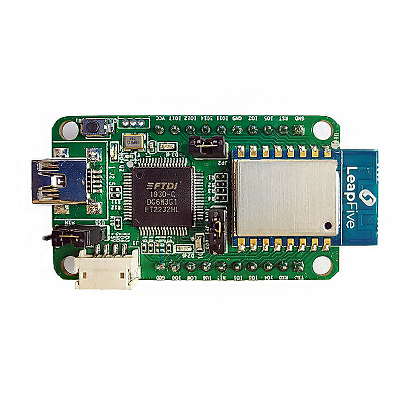
Overview
The FB-BF2-DEV-01 Development Board, embedded with the LF-WM05 module, is designed to provide developers with a convenient Wi-Fi/BLE learning platform. It features user-friendly pin headers, LED indicators, and a Reset button, making it ideal for developing Wi-Fi/BLE IoT devices.
Features
• GPIO
• All Module GPIO Pins are Exposed
• LED Indicator
• Power Indicator
• Status Indicator
• UART Transmission/Reception Indicator
• Jumper for Power Source Switching
• USB Power Supply/Independent Power Supply
• Button Functions
• Independent RESET Button
Features
|
Supports 802.11 b/g/n standards, frequency range 2400M ~ 2483.5MHz |
Peripheral |
|
Includes 276KB SRAM/128KB ROM/1Kb eFuse |
▪ 2*UART |
|
Includes 2MB/4MB XIP FLASH |
▪ 1*I2C |
|
Operating Voltage: DC 2.5 V ~ 3.6 V |
▪ 5*PWM |
|
Wi-Fi/BLE Features |
▪ 1*SPI |
| ▪ Wi-Fi supports IEEE 802.11 b/g/n standards | ▪ 1*SDIO |
| ▪ Wi-Fi supports STA, SoftAP and Sniffer modes | ▪ 1*12bit ADC |
| ▪ PCB onboard antenna | ▪ 1*10bit DAC |
| ▪ BLE 5.0 | ▪ 13*GPIO |
Development Board Real Image and Pin Definitions
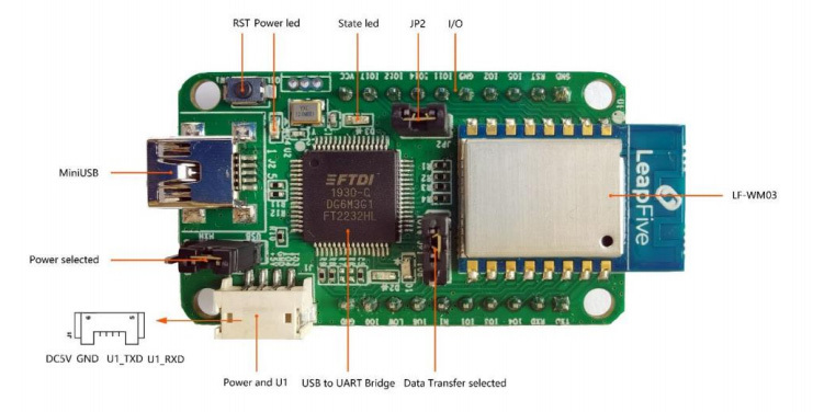
LFB-BF2-DEV-01 Pin Definition
| Components |
Component Name |
Function Description |
|
LF-WM03 |
LF-WM03 Wi-Fi Module |
IoT Module Based on LF686 |
|
I/O |
External I/O Ports |
Dual-row pin headers exposing GPIO, UART, SPI, I2C, PWM, and other peripherals |
|
JP2 |
LF-WM03 Power Short Interface |
Power control jumper for enabling/disabling the LF-WM03 module |
|
State led |
Status Indicator |
Blinks during operation mode; dim in download mode |
|
Power led |
Power Indicator |
Stays lit when the development board is powered on |
|
RST |
Reset |
Reset button |
|
Mini USB |
Mini USB Port |
DC5V power supply, program downloading, and debugging interface |
|
Power selected |
Power Selected |
Select between Mini USB power supply or Power and U1 power supply: Short the right two pins to power the board via the Mini USB port; Short the left two pins and use jumpers to connect the USB interface for power supply. |
|
Power and U1 |
4-Pin Socket |
Serial communication and DC5V power supply |
|
USB-to-UART Bridge |
USB-to-UART Bridge |
Single-chip USB-to-UART bridge, capable of providing extremely high transmission rates |
|
Data transfer selected |
Data Transfer Selection |
For firmware download, GPIO16 must be connected; this jumper is used to select GPIO8 or GPIO16 as UART0_TXD |
Development Baseboard Application

Relay Control
▪ Development and learning based on the BF2 platform for relay control applications

Temperature and Humidity
▪ Development and verification of temperature and humidity sensors

LED Control
▪ Utilize GPIO and timer applications to control LED on/off functionality

Cloud Platform Connection
▪ Learn to connect and verify applications with cloud platforms

Integrated Experiments
▪ Comprehensive experiments combining relay control, temperature and humidity sensors, LED control, and cloud platform integration
EN_BF2 Development Board (Wi-Fi/BLE)
Download
News


Video


